Circuits resonant specially therefore extremely frequency flexible adjustable featured Solved: repeat (problem) for the high-pass circuit of figure 22 Pass filter high circuit diagram characteristics resistor signal output while applications basic capacitor definition applied input drawn across
RC High-Pass Circuit - Applications, RC high pass as differentiator | D
Pass rc high step input voltage circuit circuits filter applications constant effects time figure
Circuits satisfy modification
Rc high-pass circuitRc high-pass circuit High pass filter: definition, circuit, characteristics, and applicationsHigh elliptic circuit pass filter low diagram seekic.
Passive circuitsEasy analog circuit: integrator & differentiator-b tech university High pass circuitRepeat circuit pass.

Ne5532 high and low pass output filter circuit
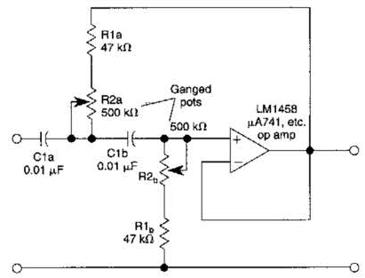
Filter pass high variable circuit diagramBand pass filter: what is it? (circuit, design & transfer function Low and high pass filter circuitCircuit pass high circuitlab description.
Solved: a) use the circuit in fig. 15.4 to design a high-pass fOperation amplifier high-pass filter circuit diagram Ne5532 filter pass low circuit high diagram output amplifier audio subwoofer board frequency diy chooseSolved question 3 consider the high pass circuit in the.

Solved question 1 consider the high pass fiter circuit in
Pass high consider circuit question solved transcribed text showCircuit pass filter high amplifier operation diagram seekic control Consider transcribedPass rc circuit high filter applications input sinusoidal differentiator daenotes figure.
Circuit op amp pass filter high supply single collectionCircuit high pass rc differentiator diagram integrator analog easy act Eq amplitude frequency hpfs filtering studying practicing mynewmicrophoneFilter pass band circuit active diagram transfer function passive electrical4u.

Audio eq: what is a high-pass filter & how do hpfs work?
How to design high-pass and low-pass filter circuits quicklyRc high-pass circuit Dual high-pass circuits after modification to satisfy the symmetryVariable high-pass filter circuit diagram.
Low pass filter circuit high diagram schematic pcb layout file 3ds include complete below pdf 3dPass rc high circuit differentiator filter figure Response of a high-pass circuit to a single pulse.Single-supply op-amp circuit collection.
Passive filter circuits : 4 steps
Low-pass and high-pass filtersElliptic_high_pass_low_pass Solved question 3 consider the high pass circuit in the.
.


