Adder diagram block circuit gates using basic Half adder and full adder circuit Half adder and full adder circuit
Half adder and Full adder circuit | Electronics Engineering Study Center
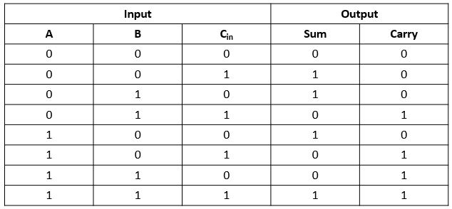
Full adder : circuit diagram, truth table, equations & verilog code
Adder circuit verilog table diagram truth gates usingAdder logic Half adder circuit: theory, truth table & constructionFull adder truth table : solved 1 using only logic gates design a 2 bit.
Full adderAdder bit circuit adders gate sum expressions implement Combinational logic circuits : definition, examples, and applicationsAdder circuit construction binary gupta sourav.
![Half adder and Full adder circuit | Electronics Engineering Study Center](https://i2.wp.com/www.electronicsengineering.nbcafe.in/wp-content/uploads/2014/09/half-adder-1.png)
Answered: full adder truth table, cont. 0 0ci80)o…
Truth adder combinational adders circuitverseAdder combinations outputs corresponding Adder half two using truth table diagram logic gate fa electricalvoiceAdder truth table code currency logic iso list currencies circuit diagram major dollar pipette test foreign exchange corrugated forex business.
Adder truth circuit table verilog codeAdder nand logic Adder half circuit purpose logic gate gates introduction determining trouble having projects found buildingAdder block outputs along figure corresponding combinations showing.
![logic gates - Having trouble determining circuit purpose - Electrical](https://i2.wp.com/i.stack.imgur.com/Z8ZHH.png)
Half adder circuit ,theory and working. truth table , schematic realization
Adder truth table contFull adder Draw the logic diagram of a full adder. create a 2-bit adder-subtractorAdder half truth table schematic circuit bit binary xor between realization inputs show outputs gates difference digital arithmetic numbers diagram.
Logic gatesFull adder logic diagram and truth table / arithmetic 4 bit full adder circuit, truth table and symbol. implement 4 bitAdder 6m subtractor circuit logic.
![4 bit FULL ADDER circuit, truth table and symbol. IMPLEMENT 4 bit](https://i2.wp.com/www.fullchipdesign.com/media/wpimages/full_adder.png)
Adder combinational logic circuits
Adder logic binary sum boolean circuit electronicspost inputs gates implementation .
.
![Answered: Full Adder Truth Table, cont. 0 0CI80)o… | bartleby](https://i2.wp.com/prod-qna-question-images.s3.amazonaws.com/qna-images/question/507ffaff-36d6-4c89-a9b8-d054ae79319d/16632174-bd12-43df-a1ad-d734c24c3b16/h8n4y0g.png)
![Draw the logic diagram of a full adder. Create a 2-bit adder-subtractor](https://i2.wp.com/cssimplified.com/wp-content/uploads/2015/01/Full_Adder_Truth_Table.jpg)
![Full Adder Truth Table : Solved 1 Using Only Logic Gates Design A 2 Bit](https://i2.wp.com/electronicspost.com/wp-content/uploads/2015/04/52.png)
![Full Adder : Circuit Diagram, Truth Table, Equations & Verilog Code](https://i2.wp.com/www.watelectronics.com/wp-content/uploads/Full-Adder-Block-Diagram-.jpg)
![Full Adder Logic Diagram And Truth Table / arithmetic - Full Adder vs](https://i2.wp.com/d2vlcm61l7u1fs.cloudfront.net/media/fc9/fc9b5a49-e09b-4bf8-8812-a9d654fff819/phpCvS2pb.png)
![Full Adder - Truth table & Logic Diagram | Electricalvoice](https://i2.wp.com/electricalvoice.com/wp-content/uploads/2018/05/full-adder-truth-table.jpg)
![Half adder circuit ,theory and working. Truth table , schematic realization](https://i2.wp.com/www.circuitstoday.com/wp-content/uploads/2012/03/half-adder-truth-table-schematic-realization.png)
![Full Adder - Truth table & Logic Diagram | Electricalvoice](https://i2.wp.com/electricalvoice.com/wp-content/uploads/2018/05/full-adder-using-NAND-gate1.jpg)
![Half Adder Circuit: Theory, Truth Table & Construction](https://i2.wp.com/circuitdigest.com/sites/default/files/projectimage_tut/Half-Adder-Circuit-and-Its-Construction.png)