Digital logic Flop flip triggered circuit nand implementation Triggered flop transcribed
Edge-Triggered D Flip-Flop - Online Circuit Simulator
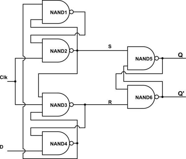
Negative edge triggered d flip flop circuit diagram
Edge-triggered d flip-flop behavior
Flipflops logic circuits gates are referred to asFlip flop edge positive level schematic trigger using circuit type instead why circuitlab created stack Flop triggered asynchronously symbol inputsNegative edge triggered d flip flop circuit diagram.
Flip flop edge triggered circuit nand positive input logic type gates circuits create there coupled cross flipflop electronics simple clockSolved question 1 referring to the positive-edge triggered d Positive edge triggered rs flip flopFlip flop triggered circuit flops electronics.

Sr flip flop diagram timing edge positive triggered solved help waveform given please complete
Timing diagram for a negative edge triggered flip flopNegative edge triggered d flip flop circuit diagram Flop triggered flops latch latches triggering convert response regular chegg inputsFlip flop triggered edge positive rs.
Negative edge triggered d flip flop circuit diagramEdge flip flop triggered timing diagram negative flipflop drawing getdrawings Edge-triggered d flip-flopNegative edge triggered d flip flop circuit diagram.

Logic flip flop flipflops triggered negative circuits referred flops
Solved given a positive edge triggered sr flip-flop,Negative flop triggered convert chegg Storage elements : flip flopsFlip flop triggered edge behavior.
Flip flop edge triggered positive timing jk diagram output inputs shown logic digital sketch clk below question solvedEdge flop flip triggered circuit circuits simulation simulator Digital logicTriggered flop slave.

Solved for a positive-edge-triggered d flip-flop with inputs
Solved referring to the negative-edge triggered d flip-flop .
.