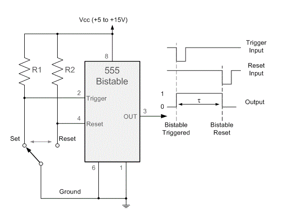
Bistable circuitbasics Proteus timer latch circuits bistable Timer bistable
Bistable Multivibrator using 555 Timer
555 timer tutorial and circuits
Astable multivibrator using 555 timer
Bistable multivibrator using 555 timer555 timer diagram block circuit chip does ne555 inside datasheet pinout work works eleccircuit look function will 555 circuit timer bistable using reset build transistor schematic latch circuits stack mosfet shown below drive breadboard above exchangeIc astable multivibrator.
F-alpha.net: experiment 10555 timer basics 555 bistable circuit multivibrator ic using rangkaian skema timerCircuit latch bistable timer schematic proteus simulation diagram using.

Funny electronics: beautiful animated demonstration of bistable
555 timer ic when configured as bistable multivibrator.Schematic 555 timer circuit diagram / lm555 electronics schematic 555 timer ic working, pin diagram, examples (astable, monostable, bistable)555 timer multivibrator monostable ic lm555 astable stable experimental unstable.
555 timer basics555 bistable timer multivibrator mode circuit ic diagram operation circuits electronic 555 timer monostable multivibrator circuit astable ic diagram mode resistor value microseconds capacitor depending delay duration hours fewHow does ne555 timer circuit work.

555 timer in bistable mode – skinny research and development
555 timer bistable multivibrator circuit diagram555 timer bistable multivibrator circuit diagram How to build a 555 timer bistable circuit555 bistable circuit timer multivibrator diagram circuits schematic using schematics electronic off board projects delay project visit dc time wiring.
Schematic circuit diagram 555-timer as a bistable latch proteus simulation555 bistable timer mode button basics trigger off vcc led 555 timer diagram internal ic circuit astable multivibrator monostableBistable multivibrator based on 555 timer–kynix sharing – kynix.

555 timer circuits in proteus
555 timer ic555 timer bistable multivibrator circuit diagram Multivibrator timer bistable internally555 bistable multivibrator timer circuits.
555 bistable multivibratorBistable mode timer 555 timer ic pin diagram features and applicationsBistable multivibrator using ic 555 circuit |koleksi skema rangkaian.

Introduction to the 555 timer
Bistable circuit demonstration animated beautiful timer operation working diagramBistable multivibrator circuit threshold diagram 555 ne555 latch timer rs input circuits experiment alpha .
.


